| Japanese | English |
Recently, we heard that one of our user had tried connecting an oscilloscope probe to the PC's microphone input terminal for measuring the circuit's response by the Realtime Analyzer. So we immediately tested this configuration.
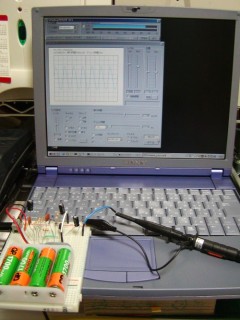
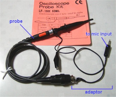
We created a cable for connecting probe's BNC connector to the PC's microphone terminal. The probe we used here is a commercially available unit that can be purchased in Akihabara (Tokyo) or Osu (Nagoya) at between 3,000 and 5,000 yen. The unit has an adjustable impedance that can be switched between 1MW and 10MW. CR oscillation circuit is used for a signal source. A 1 kHz sinusoidal wave is generated.
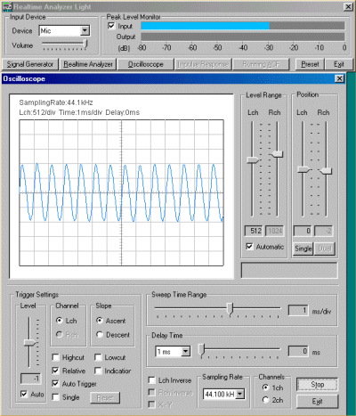
The input signal is displayed on the oscilloscope of the Realtime Analyzer. The waveform is slightly distorted, probably because of an effect of the PC's A/D converter. The unit of the oscilloscope display is the amplitude of the digitized signal. Its maximum is ±32768 at the time of 16bit sampling. To measure the actual voltage, it is required to calibrate the input signal voltage using the voltmeter. See probe2 and probe3 for how to calibrate the input voltage.
Let's look at the "Spectrum". We can see the fundamental frequency of 1 kHz and its harmonics.
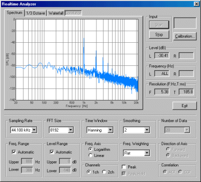
We can see the same signal in the1/3 octave band analyzer.
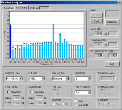
The user mentioned above connected the probe to a portable compact PC. He said that it is very convenient to be able to see rough waveforms at his own desk, in a meeting room, or at the customer's office, without going to the laboratory every time. Please keep in mind, however, that impedance matching has not been confirmed under these experimental conditions. So the observed waveforms should be used only for the reference purpose.
Note: This is an "experiment". We can neither guarantee operation nor take responsibility for the test results. When you connect a probe to your computer, please try with your own responsibility.