| Japanese | English |
A pink noise is generated by the signal generator.
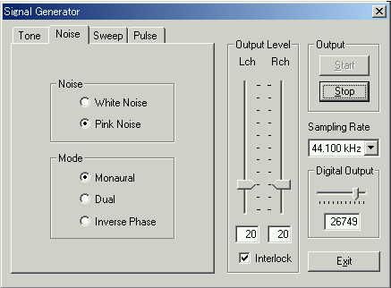
To record this signal to a measurement system, choose WAVE (MIXER) as an
input device.

The signal is analyzed by the "1/3 octave" band analyzer. The
figure below is the 1/3 octave analysis. This graph shows the frequency
characteristic of a built-in sound circuit of a computer. A vertical axis
indicates a signal level in dB for each frequency band. Generally, +-3dB as
compared with 1kHz is considered as tolerance level.
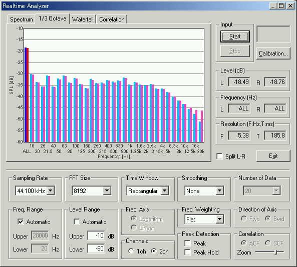
This machine (DELL, INSPIRON7500) has a problem. The high frequency region
from 4 kHz is declining immediately. To check which device is problematic, pink
noise was generated in other computer (VAIO PCG-R505R), and it was connected to
the LINE IN terminal of DELL by the mini plug cable. As shown in the figure
below, the response is quite good. In this case, it is thought that the high
frequency region is declining in the headphone amplifier of DELL. It was also OK
when putting the headphone output of VAIO into the line input of DELL. So a Line
in amplifier of DELL and a headphone output have no problem. For such a check, a
cable with a stereo mini terminal is necessary.
Adjustment of the volume of input and output
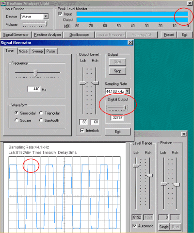
An oscilloscope is used to check a distortion of the sound signal within a computer.
First, look at a peak level display and adjust a slider type input volume.
(Adjust to be set to about -5 dB at the time of the maximum.)

The volume of input device is operating the sound mixer of Windows by remote
control, and those are interlocked. This is called "software volume."
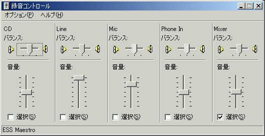
Volume control of Windows should be silent except WAVE.

On the other hand, the mechanical volume attached to the computer is called
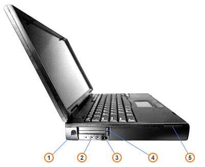
it "hardware volume." In DELL INSPIRON7500, 3 in this figure is called
a "sound volume dial".
In the signal generator (see a figure below) there is another volume control
“Digital Output”. This is the program volume (a volume which adjusts the
level of the signal to be input in AD/DA converter) that the real-time analyzer
controls. It is for making a built-in amplifier not distorted.
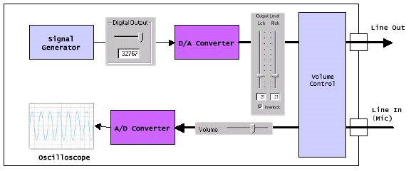
Software uses the CPU power of a computer, the D/A converter, the sound
interface, and the video output. Also, the sound mixer and sound driver of
Windows are used. When the waveform is collapsed in the oscilloscope, check a
volume control of the realtime analyzer first. If the input volume is too large,
the peak of a sine wave is deleted squarely. In this case, adjust the Digital
Output.

This is a functional composition figure inside a personal computer.
An oscilloscope is used also for a test of the software volume of a computer, or the connection impedance.
Output 1kHz sine wave with a signal generator, and check a waveform with an
oscilloscope.
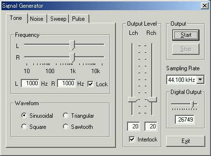
Click "Start" button to see a waveform. It automatically adjusts a
signal range in time and intensity.
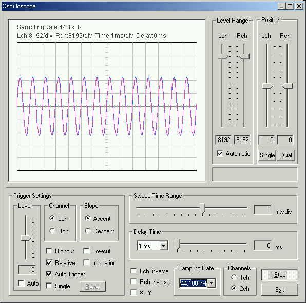
In the real time analyzer, an adjustment result can view on a measurement screen on time. It measures more simply than other methods.
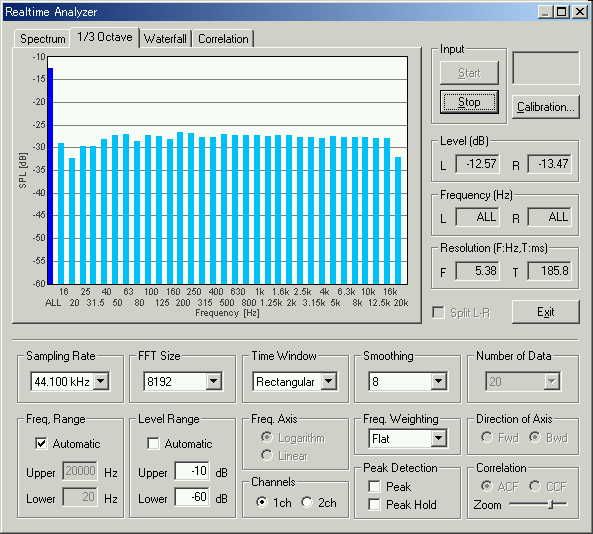
Then, generate a pink noise again and start 1/3 octave analysis. It can be
seen that the frequency characteristic of the sound circuit is adjusted
correctly.
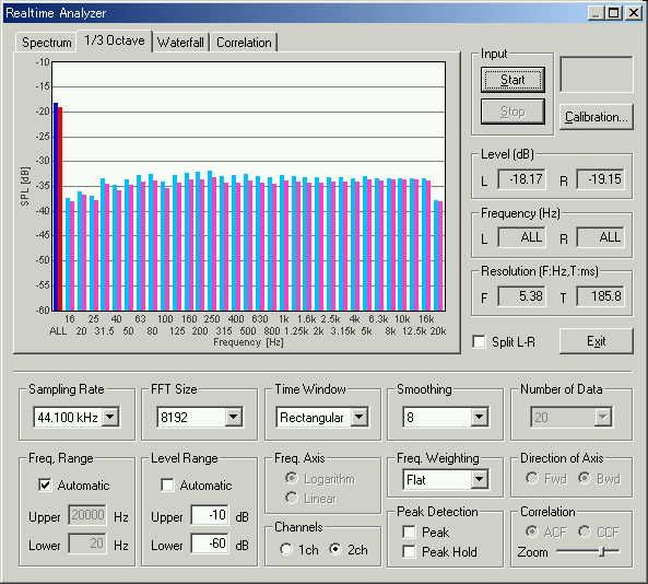
The following picture is of DELL INSPIRON 5000.
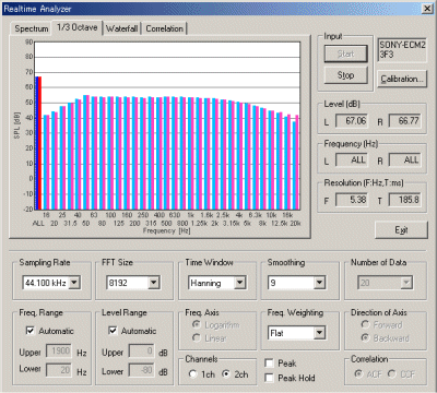
Next picture is of DELL INSPIRON 7500. When it is measured, the
characteristic is known well.
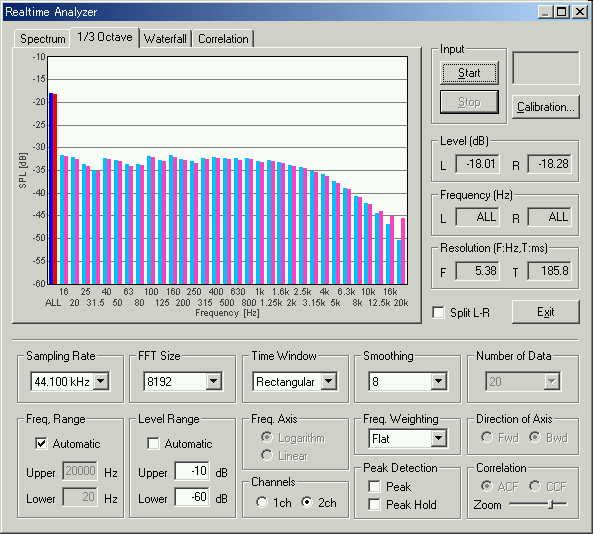
My two INSPIRON7500 machines have the same characteristic. if necessary, its frequency characteristic is easy to correct. INSPIRON7500 is totally excellent notebook PC.
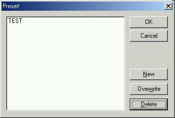
If you save the corrected state by the preset function, you do not need to
adjust a volume, input device, and so in the next time. You can call all of them
from the preset.
A measurement system needs a signal generator because it is the software which works in the common personal computer. In order that this measurement system may work in any personal computers and OS, the computer always needs to be checked whether it has sufficient performance.
The right measurement cannot be performed, if the measurement machine is broken or an adjustment and a setup are mistaken. Before measurement, a careful check is required.